Structural System
Foundation
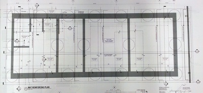
The foundation system of the FMC Tower is primarily of concrete caissons, consisting of concrete columns constructed in cylindrical shafts excavated under the proposed structural column locations. The system of and the soil beneath the building prevent the complex from moving vertically, so the system is usually used when soil of adequate bearing strength is found below surface layers of weak materials such as fill or peat. Caissons typically possess enough dead load to counteract moderate wind uplift. If additional “ballast” is needed, a contribution of the perimeter grade beams could be considered. The grade beams also engage the passive pressure-resistance of the soil and thus help resist horizontal column reactions. Caissons in the FMC Tower are 8 feet in diameter and are drilled about 50 feet below the surface to the rock. The advantages of caissons include: economic, minimizing pile cap needs, easily adaptable to varying site conditions, and high axial and lateral loading capacity.
Besides the caissons, one lower mat and one upper mat are used in the foundation system. The elevators are built on the lower mat. Mats are reinforced in two directions, both at the top and at the bottom. Heavyweight mats used in FMC Tower work well in resisting wind uplift, and their continuous reinforcement solves the problem of extinguishing the horizontal column reactions at the opposite ends of the frames. Mats possess high reliability but a low versatility, because they do not work with deep trenches, depressions, and pits. The strength of the concrete used in the foundation of the FMC Tower is high up to 10,000 psi with most of it as 6,000 psi.
Reinforced Concrete Shear Core with Steel Frame
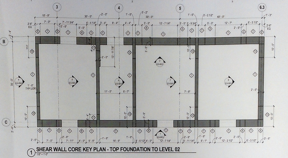
Core walls enclosing building services such as elevators, mechanical and electric rooms, and stairs have been used extensively to resist lateral loads in tall concrete buildings. The use of simple shapes such as C and I shaped walls around elevators interconnected with coupling beams constitutes one of the most typical methods of providing resistance to lateral loads.
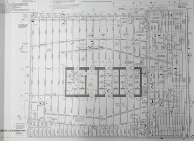
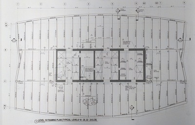
In the composite version this system, a central concrete shear wall core is designed to resist the entire lateral load while the remainder of framing surrounding the core is designed for gravity loads using structural steel, metal deck and concrete topping as the figures shown below. The walls may be reinforced conventionally with longitudinal and transverse reinforcement, or may include embedded structural steel boundary columns in addition to conventional reinforcing bars. The successful performance of such hybrid structural systems depends on the adequacy of the primary individual components which are the core walls, steel frames, and frame-core connections.
|
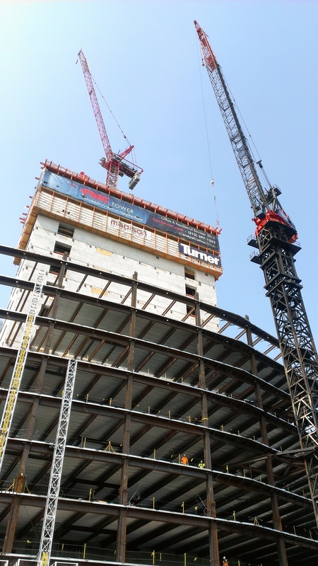
The choice of construction sequence, whether the concrete core or steel surround goes up first, is often project specific. In the FMC Tower, concrete core is built first, using jump or slip forms, followed by erection of steel surround, as shown in the figure on the right. Although structural steel erection may not proceed as fast as in a conventional steel building, the overall construction time is likely to be less because the building’s vertical transportation, consisting of stairs and elevators and mechanical and electrical services can be installed within the core while erection of steel outside of the core is still in progress. In some other buildings, steel erection columns within the shear walls serve as erection columns, and erection of steel for the entire building proceeds as in a conventional steel building. After the steel erection has reached a predetermined level, concreting of the core takes place using conventional techniques. To facilitate jumping of forms from one level to the next through the floors that are already in place, temporary openings are provided in the floor framing.
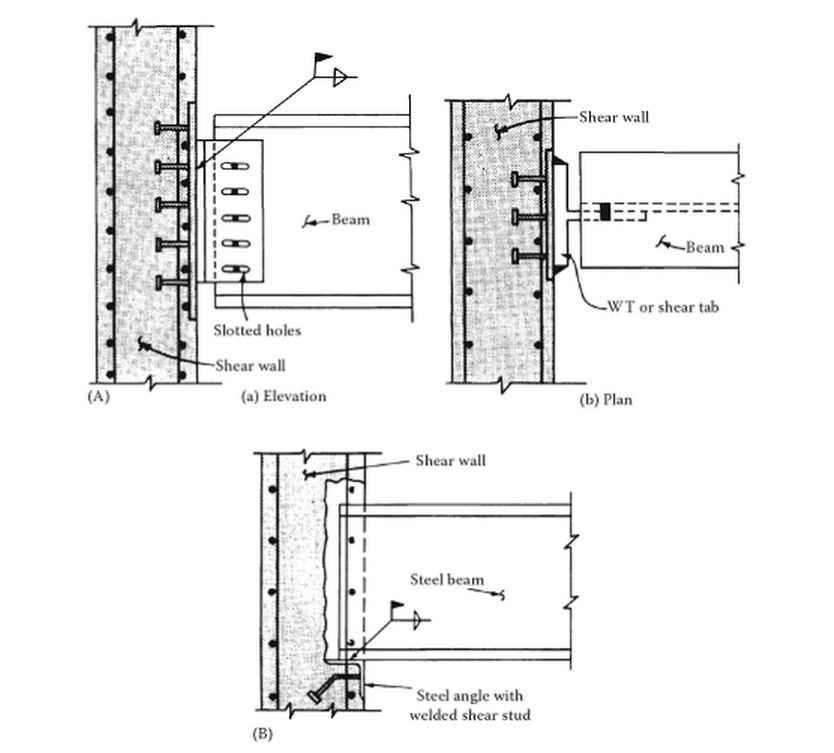
In this system, the steel surround is designed as a simple framing for gravity loads only. Since there are no moment connections with welding or heavy bolting, erection of steel proceeds much faster. The lonely nonstandard connection is between shear walls and floor beams. Various techniques have been developed for this connection, chief among them, are the embedded plate and pocket details, as shown in the figure on the left below. The floor construction invariably consists of composite metal deck with concrete topping. Since steel columns carry only gravity loads they tend to be small, both at the building interior and exterior, thus increasing the space-planning potential. |
|
The structural behavior of this type of building is no different from that of a concrete building designed to resist the entire lateral forces in the core. However, to supplement the torsional resistance of the concrete core, it is advisable to provide a reasonable lateral bracing system at the building perimeter. If the entire lateral load including those due to torsion is resisted by the central core, the steel surround may be designed as simple framing for gravity loads only. Since there are no moment connections, steel erection proceeds much faster.
The floor within the core may be constructed either in concrete or structural steel. The connection between the floor slab and core walls is often project specific. The weld plate detail shown in figure on the left (a) is, however, the most popular, particularly in a slip-formed construction. The weld plates are set with the outer surface flush with the wall surface. The plate is anchored to the wall by shear connectors welded to the plate. Experience in slip-form construction indicates that it is prudent to oversize the plates to compensate for misalignment. Subsequent to the installation of weld plates, structural tee or shear tab connections with slotted holes are filled welded to the embed plates. Slip forming is a special construction technique that uses a mechanized moving platform system. The process of slip forming is similar to an extrusion process. The difference is, in an extrusion process the extrusion moves; in a slip-forming process the die moves while the extrusion, namely the concrete, remains stationary. |
|
Advantages:
No structural steel bracing or moment connections Lowest weight structural steel Column-free tenant space High performance, stiff building Practical for office buildings taller than 20 storeys One of the most cost-effective designs to provide building frame lateral stability Disadvantages: Extended construction duration (have to build the core in advance of the building) Multiple structural steel erection mobilizations Have to rebuild the core forms at storey height transitions |
Truss
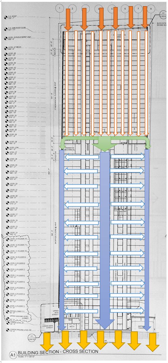
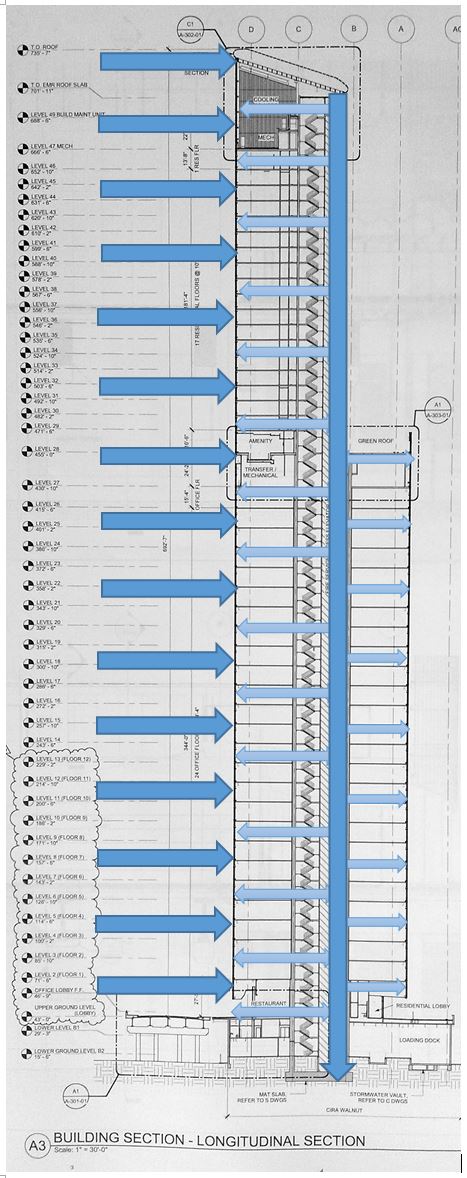
For low-to-moderate-rise buildings, up to 25 to 30 storeys, the concrete core can be used to provide a majority of the lateral force resistance. For taller buildings, the use of dual systems is more common, where the perimeter frames are engaged with the core. However, the FMC Tower is designed with two separate structures systems below and above the transition floor. The storeys 1-26 are offices, which are concrete core with steel frame structure, while storeys 29-46 are residential, where the structure is concrete frame. The steel frame will provide a taller ceiling to the offices, and the residential will only have concrete top without ceilings. Because the columns in the residential structure do not ally with those in the office structure, a transition from a forming system to a carry system and to a forming system is required.
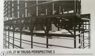
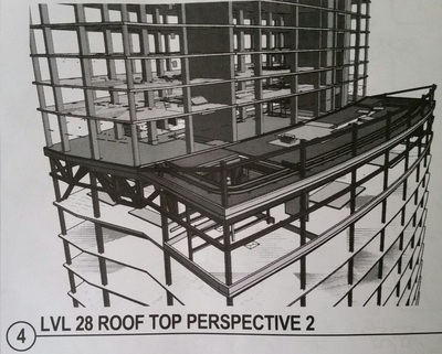
A truss system is used in the transition floor, with the height of approximately 30 feet and a total of eighteen trusses of more than ten types of functions. Plates at the foundation for the residential tower transfer loads for all the concrete structure of the residential into the transfer trusses and into the concrete core of the office storeys. A number of transfer beams are also installed on the 28th floor, and the floors above are gradually simpler in structure.
Reinforced Concrete Frame
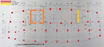
Concrete frame structure is one of the most common type of modern building. It consists of a frame or skeleton of concrete: beams, columns, and slabs. Beams are the horizontal members carrying lateral loads. Column is the most important member, as it carries primarily axial load and is generally subjected to axial load and moment. The beams and columns are connected by rigid joints. Slabs are horizontal plate elements carrying lateral loads. The frames provide resistance to both gravity and lateral loads through bending in beams and columns. Shear walls are also an important structural element, and in the residential tower, one shear wall of 1’6” thick is built. The function of a shear wall is to resist horizontal forces on buildings such as wind and seismic load, and it also carries vertical loads like the other columns do. A “concrete core” also exists in the concrete frame, but it serves as part of the columns and also as the elevator shaft.
The concrete used in the FMC Tower varies from 4,000 psi to 10,000 psi, and all concrete is required to include reinforcement. Reinforced concrete has a high compressive strength compared to other building materials, and it can withstand a large amount of tensile stress. The good fire and weather resistance and the sound proof characteristic of concrete makes it an appropriate choice for residential structure. Concrete is also one of the most economic materials. It can be easily manufactured on site when encountering the shortage in material by simply having a temporary facility in the field.
The number of the columns in the FMC residential tower is approximately 40. With more columns, the slabs can be constructed less complicated, which will make the whole structure more efficient. In common cases, the concrete frame rests on foundations, which transfer the forces from the building and on the building to the ground, but in the FMC Tower, the forces are transferred to the concrete core of the office tower as shown above.
The number of the columns in the FMC residential tower is approximately 40. With more columns, the slabs can be constructed less complicated, which will make the whole structure more efficient. In common cases, the concrete frame rests on foundations, which transfer the forces from the building and on the building to the ground, but in the FMC Tower, the forces are transferred to the concrete core of the office tower as shown above.
Load Paths
Load Calculations

