HVAC SYSTEM
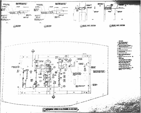
The HVAC system for the FMC Tower was designed by BALA Engineers. The mechanical system is actually made up of two systems, one for the office spaces on the lower floors, and another for the residences on the upper floors. Some components are shared, but for the most part, they are separate.
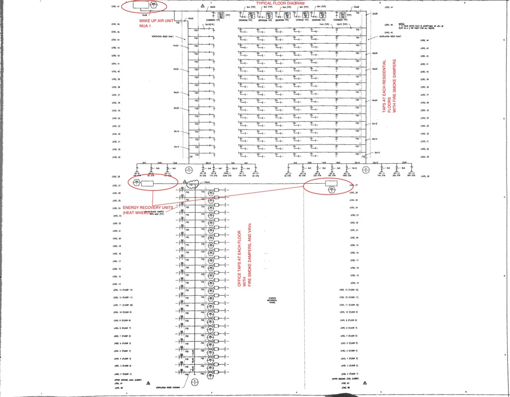
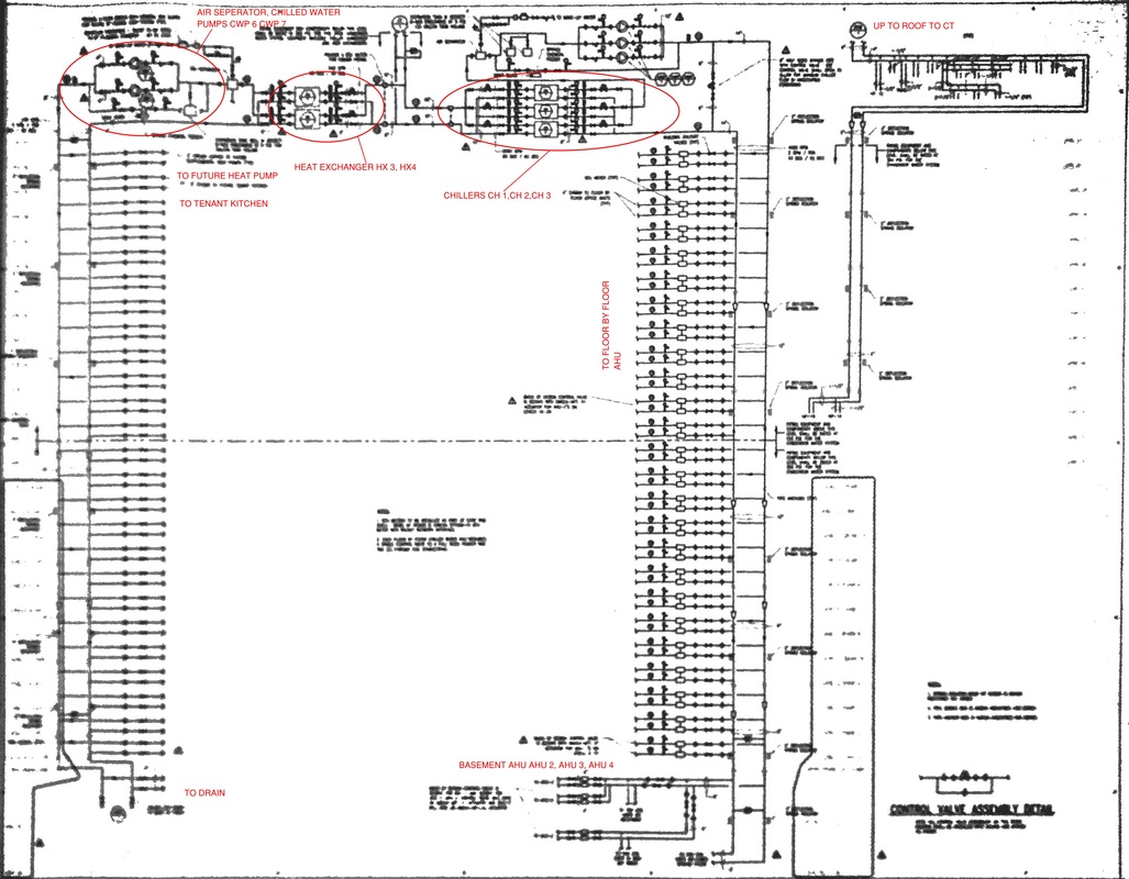
The system serving the offices has a variable air volume, floor by floor design. The air is conditioned as it flows through the air handling unit by first an energy recovery wheel which draws energy from the exhaust air, and then by a chilled water coil. The chilled water loop is made up of, three centrifugal chillers 850 ton, heat exchangers, pumps, cooling towers, and coils. Exhausting the system are exhaust fans which send the air across the energy recovery wheel. All branch take offs from the main have fire smoke dampers, as does any duct passing across a rated barrier. The spaces are heated via electric baseboard radiation.
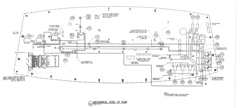
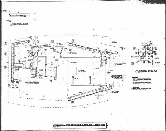
Between the two systems is a mechanical floor where some of the equipment sits. Equipment is also located in the concourse and on the roof (penthouse).
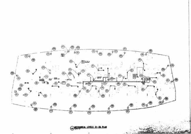
The system serving the residences is made up of heat pumps which receive some outside air from a 25,000 CFM make up air unit air handler. Air is then sent to the water source heat pumps which operate in a similar fashion to the heat exchangers except the fluids are instead of water and water are water and air. In addition to a chilled water loop, there is also a heating water loop powered by a boiler and heat exchangers. The air is then exhausted out but also passes through an energy recovery wheel. Again all the take offs from the main have fire smoke dampers as well as any duct work that passes over a rated barrier. Operating on the residential system is also a sub system made up of fan coil units which condition the air in the telecommunications rooms. These operate by introducing some outside air into the room while a fan blows the air in the room over hot or cold coils for conditioning purposes.
Design temperatures are for the summer exterior, 95 degrees F, at 53% humidity. Winter exterior design temperature is 10 degrees F and interior is 70 degrees F.
SYMBOLS, ABBREVIATIONS, AND SCHEDULES
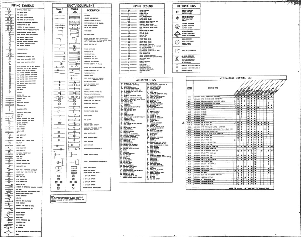
Symbols, Abbreviations, and Drawing IndexSheet for reference to those not involved in the design of the mechanical system, details the abbreviations and symbols used in the drawings. Also serves as a table of contents for the drawing set
|
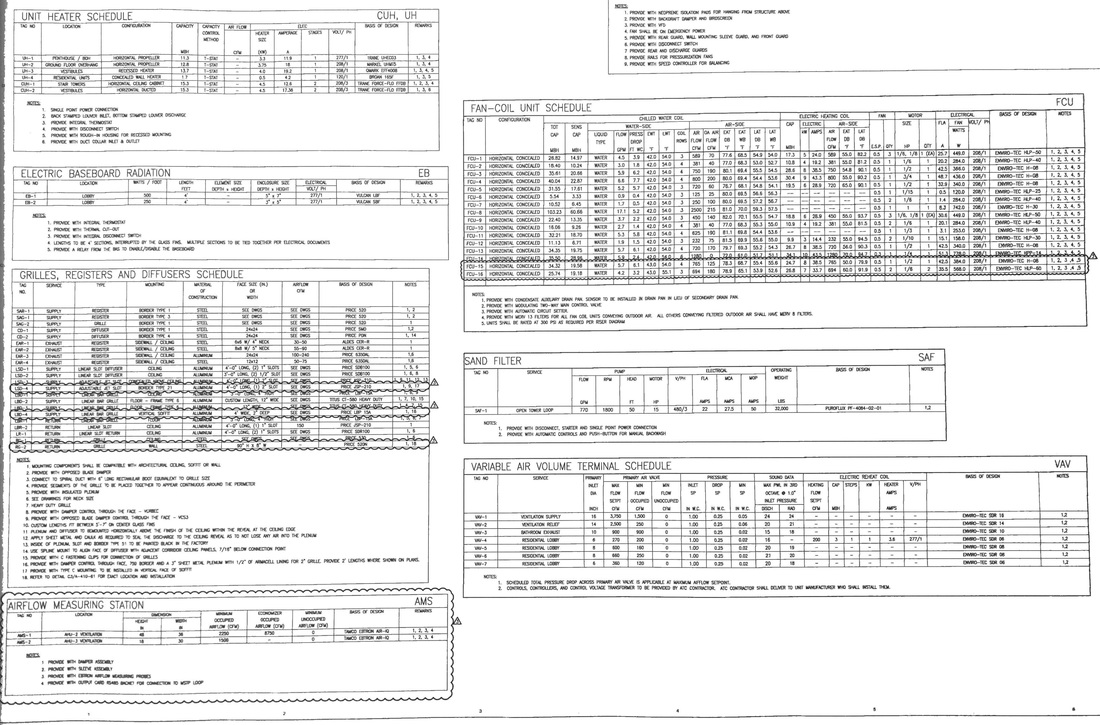
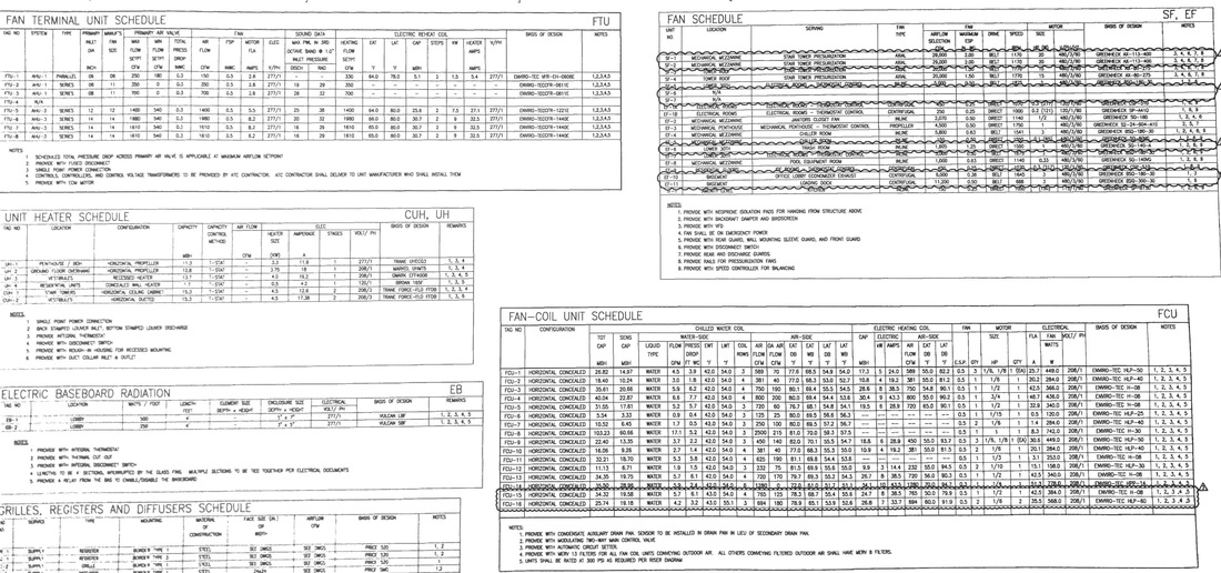
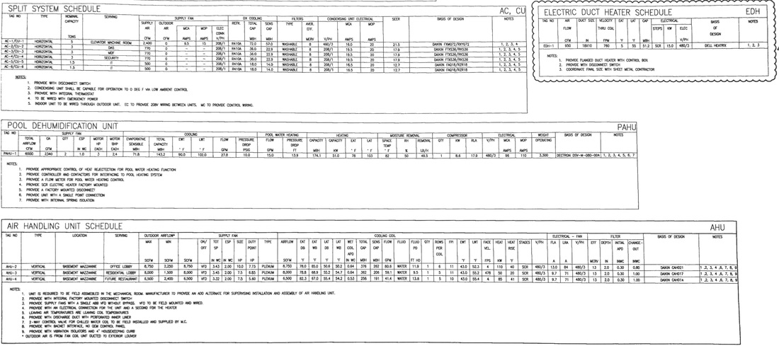
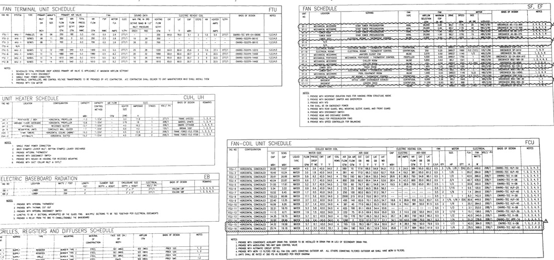
ScheduleDescribes in detail the requirements of each piece of equipment and the equipment's capacity
|
Schedule
Describes in detail the requirements of each piece of equipment and the equipment's capacity
SINGLE LINE DIAGRAMS
Mechanical Supply RiserHVAC air supply diagram, shows both offices (served by floor by floor AHUs and VAVs) as well as the residential spaces (served by a make up air unit and heat pumps)
|
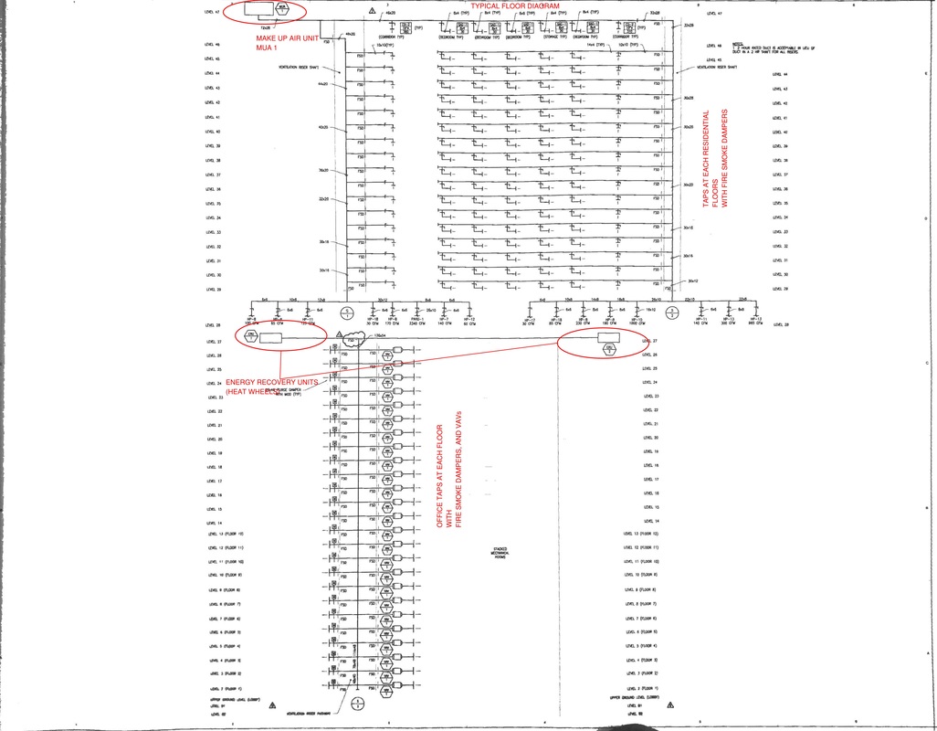
Mechanical Exhaust RiserHVAC exhaust diagram, shows exhaust air leaving via three pathways, two in the office (office exhausting out through VAVs and the through energy recovery units, janitorial closets exhausting through via a CAV system and exhaust fan 2). The residential system is
|
Office Condenser WaterThe chilled water loop actually consists of two loops. ‘Loop
A’ starts at the chiller, where water is cooled, it then enters a heat exchanger
where the cold water absorbs heat from water running through the heat exchanger
on ‘Loop B’. Next the water goes to the cooling tower where cool air is induced
on the water to cool it back down. The water then returns to the chiller to
start the process over again. The water in Loop B that transferred its heat to
the water in Loop A is cooled in the same process, it then flows to the cooling
coils in the floor by floor air handling units to cool the air, which heats the
water. The water then returns to the heat exchanger to start the process again.
|
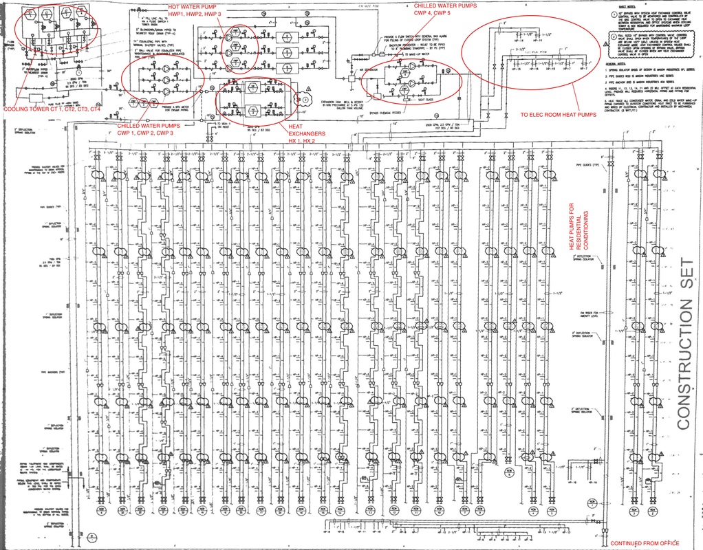
Residential Condenser WaterCondenser water diagram for the offices and electrical rooms. The loop runs through heat exchangers 1 and 2, and the cooling towers. The condenser water then conditions the residential apartments as well as the electrical rooms via heat pumps
|
Stair Pressurization |
|
|
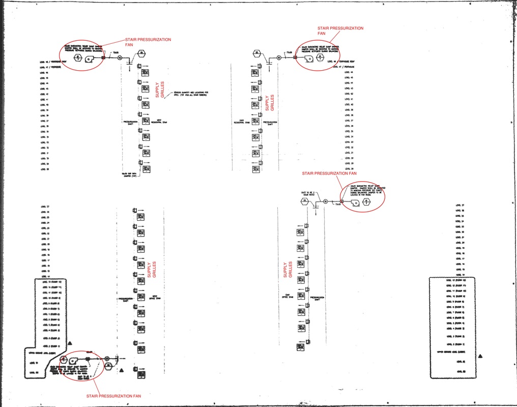
Single line diagram detailing the stair pressurization system. The stair is pressurized by use of stair pressurization fans as well as fire smoke dampers. It is important to pressurize the stair, so in the event of a fire the stair will have positive pressure and no smoke will get in the stairwell.
|
|
