Stormwater Management System
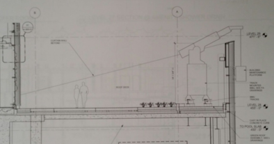
The FMC tower is designed with a water retention system to meet Philadelphia’s requirements of land owners to retain the first 1 inch of water from a 24hr design storm for a period of 24 hours before releasing the water into the city combined stormwater and sewage system. The building includes an 8200 SF green roof that and a total site area of 35,145 SF that is 100% impervious. To meet the requirements for the FMC tower, the site must be sized to retain a total of 2930 CF of water. The green roof helps to divert water from the storage tank. Information on the designed retention of the green roof was not provided, but if the green roof was designed to retain 1 inch of water it would reduce the storage tank size by 684 CF. A cross section of the green roof is presented as Figure 1. Form the rendering, the soil depth was measured at 6 inches and was judged to be and intensive roof garden because of the depth and architectural renderings. The assumed storage design of the green roof is reasonable due to the depth of the soil medium on the green roof, but much of the green roof will be covered with decking and a patio to be used as an outside relaxation space and for group yoga and fitness activities which will reduce the capacity.
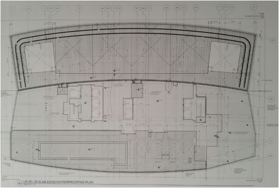
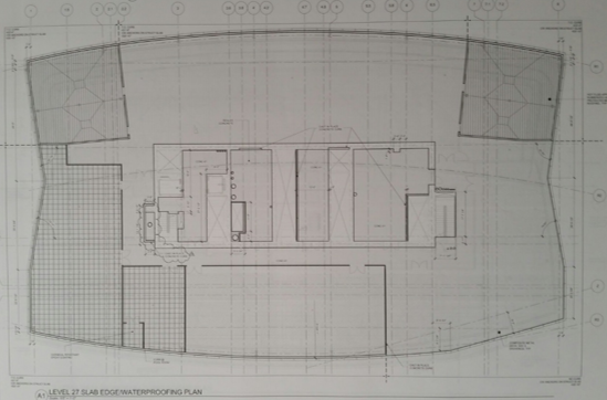
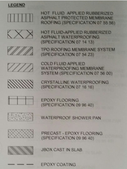
The green roof deck of the Level 28 (Amenity Floor & Green Roof) Water Proofing Plan, Figure 2, is protected with hot fluid rubberized asphalt protected membrane roofing. The area protected with this waterproofing is identified with vertical hashing. Additional slopes in the slab can be identified by the large X marks on top of the waterproofing. Symbolize the slope of the slab down to the drain at the intersection. The drains are connected to storage tanks that are placed below the two square sections that are not marked with waterproofing vertical hash. The top left and right corners are marked of the Level 27 Water Proofing Plan, Figure 3, with vertical hash depicting the slab covered with hot fluid rubberized asphalt protected membrane roofing. These areas house collection tanks for the excess stormwater and then the water is passed to the stormwater riser pipe.
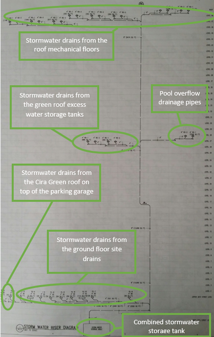
The stormwater riser system is presented in Figure 5 as a line diagram. The piping network collects water from the green roof, the top three mechanical floors and roof, overflow from the pool on the amenities floor, drains on the around the site on the ground floor and some water excess water from Cira Green, the green roof on top of the parking garage. All the water is collected in a large storage tank located below the FMC tower. Because of the additional collection from Cira Green, the storage tank would need to be sized to retain this extra load to meet the stormwater management requirements for both the FMC Tower site and the parking garage. The new capacity is estimated to be greater than 2930 CF. The exact size was not found in the construction documents and is hard to determine due large variation in the assumed load from Cira Green.
Referenced Figures
Figure 1: Green roof section showing the layers of the growing medium, waterproofing and supporting slab. The depth of the soil, 8 inches, suggests an intensive green roof
Figure 2: Level 28 (Amenity Floor & Green Roof) Waterproofing Plan
Figure 3: Level 27 (Office Mechanical & Structural Transfer Floor) Waterproofing Plan
Figure 4: Legend of the waterproofing materials used on Floors 27 and 28
Figure 5: Line Diagram of the stormwater riser diagram showing the drainage pipe network
